
This blog post takes a deep dive into the intricacies of communication over the web with the IP (Internet Protocol), its layers involved and the TCP/IP protocol suit. By the end of the post, you’ll have a good insight into how machines communicate/exchange data over the internet.
With that being said. Let’s get on with it.
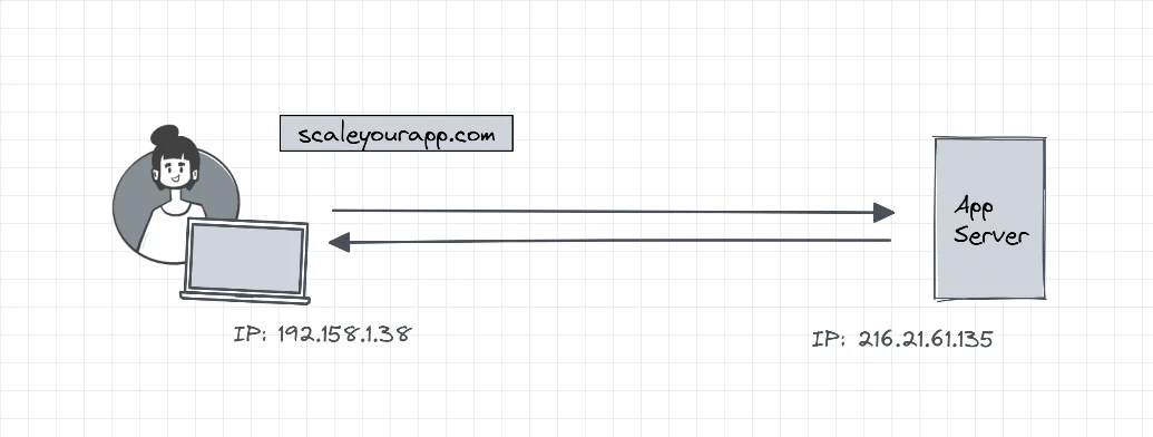
Picture a user requesting data from a server. In order to get in touch with the server, the user’s machine should know the IP address of the server and the server should know the IP address of the client to send the response. This makes IP address an essential component of web communication.
IP (Internet Protocol)
Every machine online has an IP (Internet Protocol) address via which they communicate with each other over the internet. The IP address is a unique identifier assigned to devices and DNS resolvers translate the human-readable domain names into IP addresses to enable end users to connect to an IP without the need to memorize the hard-to-remember IP addresses.
The internet protocol is a standardized set of rules that help machines, using different software and hardware, send packets to each other reliably.
Besides leveraging the IP, machines use transport protocols like TCP (Transmission Control Protocol) and UDP (User Datagram Protocol) to handle the data exchange.
The most widely used transport protocol today is the TCP since it enables reliable data exchange between machines over the internet. The Internet today runs on the TCP/IP model, whether it’s the communication between the client and the server, sending emails or files and so on. This suite of protocols is also widely used to build enterprise networks.
Now, let’s understand the various IP layers that are involved in the communication between two machines over the web with the help of the OSI model.
IP Layers
Understanding the OSI (Open Systems Interconnect) model and the associated layers
We use the OSI model as a reference for understanding network communication. The model consists of seven layers, with each layer having its specific role. These layers are the application layer, presentation layer, session layer, transport layer, network layer, data link layer and physical layer.
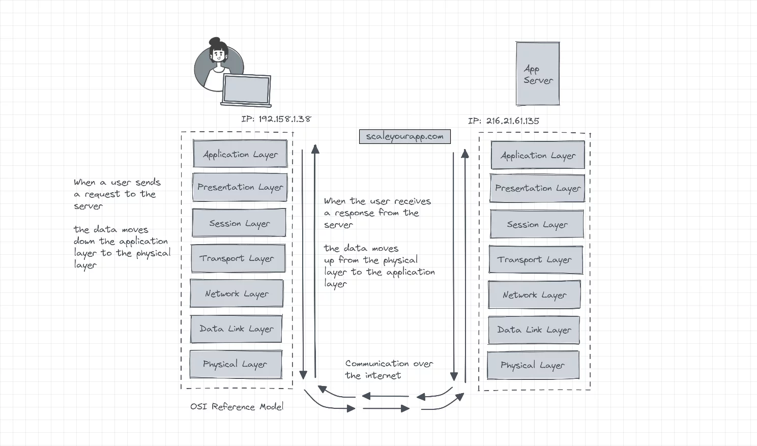
Each layer in the model executes its function powered by a number of protocols. Let’s understand each layer individually, beginning with the application layer.
Application layer
The application layer interacts with the user applications. For instance, web browsers rely on the application layer to communicate with the network. This layer contains protocols like HTTP, SMTP, FTP, NFS, DNS, etc.
Presentation layer
The presentation layer prepares data to be consumed by the application layer. Two machines communicating over the network may send data in different encoded formats. The presentation layer converts the data into a form that can be understood by the application layer of the respective machines. Data compression and encryption also happen over the same layer.
Session layer
The role of the session layer is to initialize and manage the communication between the two devices with the help of sessions. A session is the time span between the initialization and termination of the communication.
Besides managing sessions, this layer also maintains checkpoints in data transfer. For instance, if a file of 900 MB is being downloaded by a machine, the session layer will keep checkpoints of, for example, 10 MB throughout the download. In case the session breaks with, say, 322 MB downloaded, the download in the following new session will start from 320 MB as opposed to starting all over again.
This feature averts the need to download a large file all over again, over and over in case of an unstable network connection.
Transport layer
The transport layer involves breaking up data into segments before being pushed to the underlying layer. And when receiving data from the below layer, it reassembles segmented data before moving it up to the session layer. This layer is also responsible for flow control and error control in network communication. More on this up ahead.
Network layer
The network layer further breaks the segments obtained from the transport layer into packets which are later routed through the optimum network path to reach the destination.
Let’s have an insight into what packets are.
Packets
The data moves across the network in the form of packets. Packets are a basic unit of communication over the web. Besides the payload, they contain meta information like the origin, destination, index (for the destination to order the packets correctly to make sense of data), transport protocol and so on, in the header.
This meta information helps the network process packets exchanged by a number of devices. The network can also send packets via different network paths in case of congestion, which would not be possible if the data wasn’t segmented into packets. A big chunk of data moving through the network could congest the network.
Data link layer
The data link layer further breaks the packets obtained from the network layer into frames and moves them to the physical layer. This layer manages the flow and error control in intra-network communications. Also, frames are primarily used in intra-network communication and packets are used in inter-network communication which is communication over the internet.
Physical layer
The physical layer contains physical data transfer components, such as cables, switches and wireless routers. It converts data into bits of 1s and 0s and transmits it to the destination.
Now that we have a fundamental understanding of the OSI model, let’s understand the TCP/IP model.
TCP/IP model
TCP/IP (Transmission Control Protocol/Internet Protocol) model is the core of communication that happens over the web and is a suite of data communication protocols. It’s based on open protocol standards that are agnostic of the underlying hardware or operating system and can be run over an Ethernet, an optical network, a dial-up line, a DSL connection and arguably any form of physical transmission medium.
TCP abstracts away most of the intricacies and complexities of network communication from our applications. This may include handling data congestion, ensuring data delivery with accuracy and integrity, averting the network from being overwhelmed with excessive data with the help of different network algorithms, and so on.
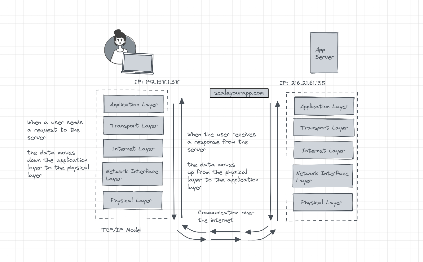
TCP/IP model layers/architecture
As opposed to seven, which the OSI model contains, the TCP/IP architecture has five layers. They are the application layer, transport layer, internet layer, network interface layer and physical hardware layer.
Application layer
The TCP/IP application layer, just like the OSI model, interacts with the user applications. It includes protocols like HTTP, FTP, SMTP, DHCP, etc.
The TCP/IP model does not have the presentation and the session layer which the OSI model contains. The application layer directly interacts with the transport layer performing the roles of all three layers combined (application, presentation and the session layer).
Transport layer
The transport layer facilitates data exchange establishing host-to-host connectivity independent of the underlying network, ensuring orderly data delivery with accuracy. The lost packets are resent and the duplicate data is discarded.
Besides handling error control, segmentation, flow and congestion control, this layer also handles application addressing with the help of ports.
Ports
A port is not a physical connection but rather a virtual logical connection managed by the machine’s operating system. A port number is always associated with an IP address. When building web applications on our local machine, you might have encountered applications running on https://localhost:8080
8080 is the port number on the application server that we run on our local machine. Port 80 is associated with HTTP. So, when we make an HTTP request to a server for a web page, we communicate via port 80 of the server.
IP address helps us determine the machine we intend to connect with and the port number helps us determine the service or the program running on that machine we intend to interact with. The service can be an email service, a web page, an FTP service and so on.
So, if we connect to a domain, for instance, like, google.com, the TCP/IP connection from our system to the remote server will be something like this:
TCP 192.168.21.201:29323 23.72.104.161:8543 ESTABLISHED
As you can observe, our system has an IP along with the port number 192.168.21.201:29323 and the remote server has an IP along with its port 23.72.104.161:8543. You can run the “netstat” command in your operating system terminal to view the connections your system makes with the websites, along with their IP and ports.
Port numbers are reserved for specific services. For instance, all the HTTP connections hit port 80 on a server, HTTPS port 443. All the FTP connections hit port 21, SSH port 22, email port 25, DNS port 53, NTP port 123 and so on. Ports help servers understand the function they have to perform with the data they receive over different ports. A client can hit different ports of a server to execute different processes. All this communication over different ports is facilitated by the transport layer.
Internet layer
The internet layer receives segmented data, aka segments from the transport layer, calling it datagrams. Every layer in the TCP/IP model has a different name for the data it deals with. The application layer calls it data streams, the transports layer calls it segments, and the internet layer datagrams.
The internet layer handles the reliable routing of datagrams across different networks through the internet to reach the destination.
Network interface layer
This layer converts datagrams into frames to be transmitted to the destination through the physical layer. The network layer is in charge of dealing with the local network the machine is attached to before the data is routed to other connected networks on the web via gateways.
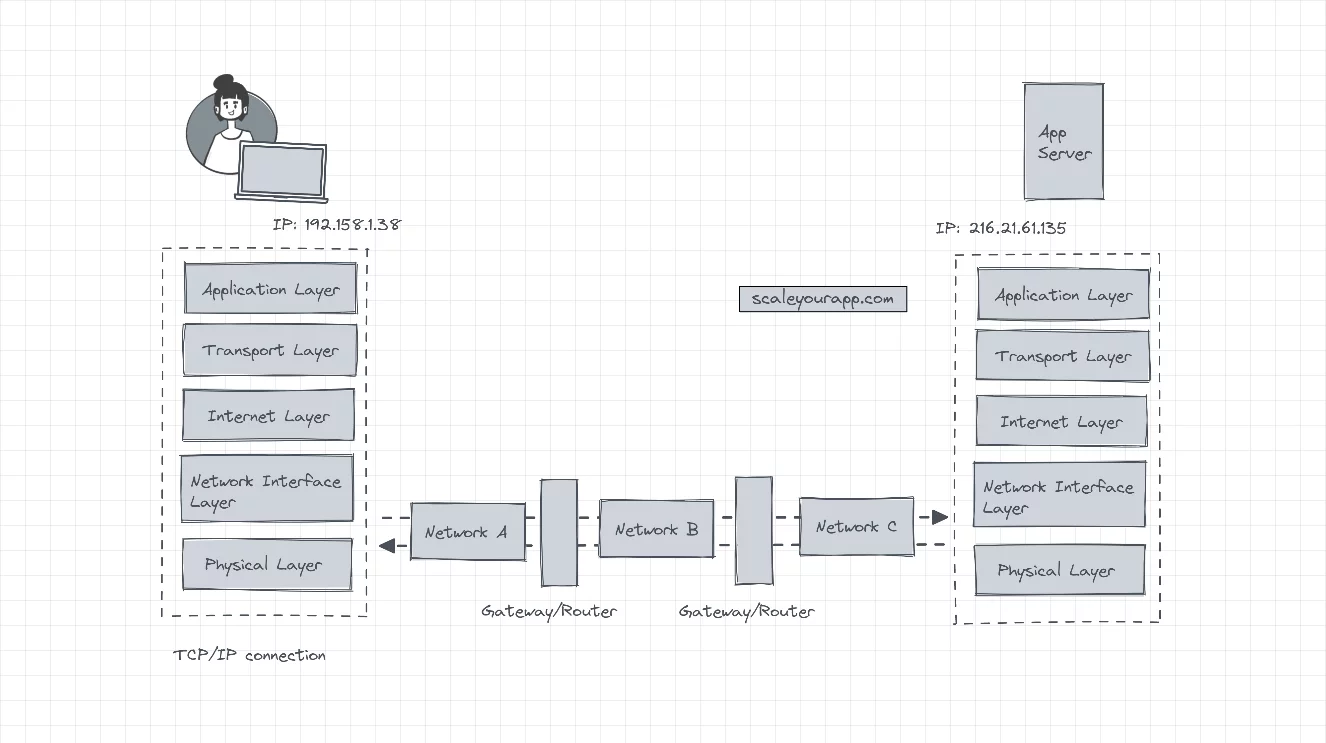
The client machine sends the data to a gateway via network A. From there, the data is forwarded to another gateway via network B. And then, via network C, the data is finally forwarded to the destination.
The client has no knowledge of other networks (B and C) in the route to the destination. It just forwards the data to the first gateway via the network it is connected to, i.e., network A.
The network interface layer must be aware of the intricacies of the underlying network to accurately transmit data without any errors. Often the TCP/IP network interface layer carries out the function of the network, data link and the physical layers of the OSI network.
Physical layer
The physical layer does the same job as the OSI model physical layer, i.e., transmitting data to the destination via physical hardware. This layer can also be a part of the network interface layer in the TCP/IP model.
These were the layers of the TCP/IP model. Now let’s understand how the TCP/IP model reliability transmits data to the destination, simultaneously managing the flow control, errors and network congestion.
If you wish to understand web architecture, including concepts like how DNS converts domain names to IP addresses, how load balancers work and more, check out my Web Application and Software Architecture 101 course.
How does the TCP/IP model transmit data to the destination reliably with flow control, error and network congestion management
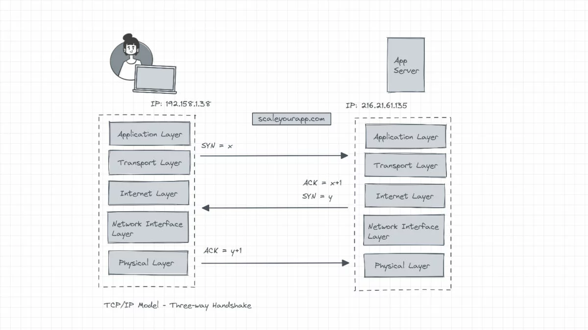
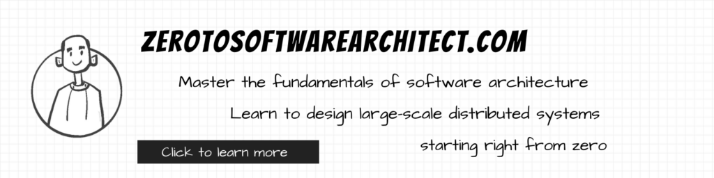
Three-way handshake
All TCP/IP connections start with a three-way handshake before any data is transmitted between the client and the server. The client sends a sequence of numbers to the server, indicating it needs to establish a connection (SYN = x). This sequence number is used as a starting number for the data segments that are sent to the server. Additionally, this sequence of numbers helps maintain the order of the data transferred between two machines communicating over TCP/IP.
The server on receiving the sequence increments it by 1, uses it as an acknowledgment (ACK = x+1), picks its own random sequence number (Y) and reverts with its sequence number and the acknowledgment (SYN=y, ACK = x+1). The client receives the data, increments the sequence number sent by the server by 1 and resends a message to the server as an acknowledgment (ACK = y+1) completing the handshake.
Once the TCP/IP connection is established after a successful three-way handshake, the client begins sending the data to the server.
When the data transfer is complete, the client sends a “no more data from the client” message to the server and the server reverts with an acknowledgment. The TCP/IP model eventually closes the connection.
Now, since every TCP/IP connection performs a three-way handshake before beginning to transfer data, this adds some latency to every connection, which makes reusing existing connections a good strategy to cut down latency.
Congestion control
In a situation where the arrival time of the acknowledgment of a packet received by the server exceeds the configured retransmission time of a packet, in case the client doesn’t receive the acknowledgment, the client will push additional copies of the packet into the network, causing congestion.
To address this, each machine in a TCP connection communicates a window size which is the size of the available buffer space it has to hold incoming data. When a connection is established, both machines communicate their initial window size to avoid creating network bottlenecks.
And this window size is dynamic. In case a machine is unable to process new data, it reduces its window size to zero, which means the other machine needs to stop pushing new data to the network. This dynamic updation of window size continues throughout the lifetime of a TCP/IP connection.
Difference between the OSI model and the TCP/IP model
The OSI model is largely used as a reference to understand the layers of the network, in contrast to the TCP/IP model that drives internet communication.
Applications leverage the TCP/IP model to run low-latency communication over the web. For instance, Spotify leverages a TCP congestion algorithm developed by Google called BBR to cut down its streaming latency.
Spotify leverages BBR, a TCP congestion control algorithm
Spotify stores music tracks in files on HTTP servers across the world. When a user plays a song, the file is fetched from the server via an HTTP GET request.
The server sends data to the Spotify client in TCP packets. The client confirms the data by sending an acknowledgment to the server. The congestion control algorithm tracks the data transmitted by the server and the acknowledgments sent by the client to maintain a healthy data flow rate between the client and the server.
The BBR algorithm builds an internal model of the connection capacity measuring the current bandwidth and maintains the send rate even in case of a minor packet loss. This is unlike other congestion control algorithms like CUBIC, which overreact even to minor packet loss, possibly pausing the network communication.
Spotify has two primary metrics to track the smooth streaming of music:
- Playback latency: this is the time from click to sound.
- Stutter: the number of skips/pauses during playback. This typically happens when the bandwidth is low.
With the TCP congestion control algorithm, they were able to reduce the stutter by 17% and 12% in Asia Pacific and Latin America and by 5% in Europe and North America. Here is a detailed read on this.
Folks, this is pretty much it. If you found the content helpful, consider sharing it with your network for more reach. You can read more about me here. Check out the post on application architecture for insights into web application architecture. Check out my intricacies of system design series on this blog.
If you wish to master the fundamentals of web architecture, check out the Zero to Software Architect learning track I’ve authored.
You can subscribe to my newsletter to get the content published on this blog and more directly in your inbox. I’ll see you in the next post. Until then, cheers.
Follow Me On Social Media